

Designing and manufacturing highly engineered gears and gearboxes
 When designing custom gears and gearboxes for a dynamic test system application, there are times when a highly engineered solution is required, rather than an off-the-shelf option. To guarantee years of operation and ensure that accurate evaluations of the test subjects are a precise snapshot without any influence from the test machine itself, a rigorous design and build process must be followed. Failure to treat the test machine gearbox in a highly engineered manner can result in premature failure and erroneous test results. At a minimum, a regimented, highly engineered solution is essential when:
Speed and torque requirements of a dynamic testing system push operating envelopes to extremes
Performance of the gears must not have an impact on or influence the recorded performance of the test article
A rigorous, 12-step process is required to ensure that a dynamic test system has a long and trouble-free machine life.
1. Evaluate design criteria and geometric constraints
Either a customer-created scope of work (SOW) or an internally created document based upon the performance requirements of the machine end use creates the project’s foundation.
2. Calculate speeds, torque, and loads
The function of each test machine is to provide outputs that will apply some range of rotational speed through a range of torque or other loads under simulated operating conditions, either for a pre-determined period or until failure. If not provided in the SOW, the speeds, torque, and load values should be determined by the machine requirements.
When designing custom gears and gearboxes for a dynamic test system application, there are times when a highly engineered solution is required, rather than an off-the-shelf option. To guarantee years of operation and ensure that accurate evaluations of the test subjects are a precise snapshot without any influence from the test machine itself, a rigorous design and build process must be followed. Failure to treat the test machine gearbox in a highly engineered manner can result in premature failure and erroneous test results. At a minimum, a regimented, highly engineered solution is essential when:
Speed and torque requirements of a dynamic testing system push operating envelopes to extremes
Performance of the gears must not have an impact on or influence the recorded performance of the test article
A rigorous, 12-step process is required to ensure that a dynamic test system has a long and trouble-free machine life.
1. Evaluate design criteria and geometric constraints
Either a customer-created scope of work (SOW) or an internally created document based upon the performance requirements of the machine end use creates the project’s foundation.
2. Calculate speeds, torque, and loads
The function of each test machine is to provide outputs that will apply some range of rotational speed through a range of torque or other loads under simulated operating conditions, either for a pre-determined period or until failure. If not provided in the SOW, the speeds, torque, and load values should be determined by the machine requirements.
 Each intermediate shaft speed and transmitted load must be calculated to ensure that the gears, shafts, and bearings can survive under maximum conditions for the expected life of the machine. Calculations are made and charted for each gear/shaft until the input interface is reached, usually at a point where a motor is sized and applied.
Factors that affect the number of gear meshes, from input-to-output, relate to the output speed and the practical ratio change per mesh, as well as the geometric constraints of the test article. The number of gear stages or meshes to achieve the output location(s) will determine the size, shape, and design of the gearbox housing and its mounting considerations.
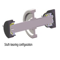
3. Determine gear shaft designs and support
Each intermediate shaft speed and transmitted load must be calculated to ensure that the gears, shafts, and bearings can survive under maximum conditions for the expected life of the machine. Calculations are made and charted for each gear/shaft until the input interface is reached, usually at a point where a motor is sized and applied.
Factors that affect the number of gear meshes, from input-to-output, relate to the output speed and the practical ratio change per mesh, as well as the geometric constraints of the test article. The number of gear stages or meshes to achieve the output location(s) will determine the size, shape, and design of the gearbox housing and its mounting considerations.
3. Determine gear shaft designs and support
 This stage of the design process is critical to ensure efficient, quiet, and trouble-free gearbox life. Calculations are performed and checked by the engineering design team and then verified by the advanced analysis team for accuracy and completeness.
Free-body diagrams are created for each gear interface to ensure that all forces to be experienced are applied and fully understood. These forces are then analyzed for their impact on the component’s operation.
Proprietary and commercially available engineering tools are used to provide values and verification of:
Gear tooth stresses
Bending stresses
Contact ratios
Module selection
Helix angles
Gear face width requirements
Shaft deflections
Shaft fatigue limitations/utilization
Gear profile modification/crowning
Lateral/torsional vibrational analysis
4. Select bearings and mounts
Bearing selection can become an iterative process and is influenced by many of the calculations in Step 3. The radial and axial forces at play, as determined by the free-body diagrams as well as rotational speed, have the major impact on the bearing selection process; however, other factors such as gear and shaft sizing due to geometric constraints, required design life (L10 life), bearing availability, and costs all play a role in the ultimate selection decisions.
Practical design factors are brought into play, such as ease of assembly and disassembly, bearing mounting and pre-loading, as well as the ability to supply proper lubrication to the bearings.
5. Determine gear/shaft manufacturing methods and materials
Now determine if gears will be separate from and keyed to the shafts or integral to the shafts. Gear processing decisions are made including the selection of the gear materials, (usually aircraft quality 8620 or 9310 steels), carburizing and heat-treatment specifications, gear grinding requirements, isotropic superfinishing requirements, and gear/shaft balancing specifications.
All gears produced must be accompanied by material certifications, heat treating certifications, grind profile charts, nital etch and magnetic particle inspection reports, and dimensional inspection reports. With the collection of this documentation, each gear has a unique birth history record.
6. Evaluate and verify design & construction
The design of each gearbox is generally determined by the geometric constraints of the test machine or application, predominantly the required locations of inputs and outputs and the number of gear shafts necessary to span the input and output centers. Machine function will determine the complexity of the gearbox construction and is an important factor in gearbox material selection.
Regardless of the material selection, all gearboxes must undergo complete finite element analysis (FEA) and modal analysis. Bearing separation forces and all external loads and forces are considered when performing FEA to ensure that gearbox construction is sufficiently robust to meet the machine demands. Modal analysis is performed to ensure that the natural frequencies of the gearboxes fall outside of the operating range of the machine performance envelope.
This stage of the design process is critical to ensure efficient, quiet, and trouble-free gearbox life. Calculations are performed and checked by the engineering design team and then verified by the advanced analysis team for accuracy and completeness.
Free-body diagrams are created for each gear interface to ensure that all forces to be experienced are applied and fully understood. These forces are then analyzed for their impact on the component’s operation.
Proprietary and commercially available engineering tools are used to provide values and verification of:
Gear tooth stresses
Bending stresses
Contact ratios
Module selection
Helix angles
Gear face width requirements
Shaft deflections
Shaft fatigue limitations/utilization
Gear profile modification/crowning
Lateral/torsional vibrational analysis
4. Select bearings and mounts
Bearing selection can become an iterative process and is influenced by many of the calculations in Step 3. The radial and axial forces at play, as determined by the free-body diagrams as well as rotational speed, have the major impact on the bearing selection process; however, other factors such as gear and shaft sizing due to geometric constraints, required design life (L10 life), bearing availability, and costs all play a role in the ultimate selection decisions.
Practical design factors are brought into play, such as ease of assembly and disassembly, bearing mounting and pre-loading, as well as the ability to supply proper lubrication to the bearings.
5. Determine gear/shaft manufacturing methods and materials
Now determine if gears will be separate from and keyed to the shafts or integral to the shafts. Gear processing decisions are made including the selection of the gear materials, (usually aircraft quality 8620 or 9310 steels), carburizing and heat-treatment specifications, gear grinding requirements, isotropic superfinishing requirements, and gear/shaft balancing specifications.
All gears produced must be accompanied by material certifications, heat treating certifications, grind profile charts, nital etch and magnetic particle inspection reports, and dimensional inspection reports. With the collection of this documentation, each gear has a unique birth history record.
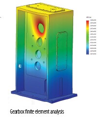
6. Evaluate and verify design & construction
The design of each gearbox is generally determined by the geometric constraints of the test machine or application, predominantly the required locations of inputs and outputs and the number of gear shafts necessary to span the input and output centers. Machine function will determine the complexity of the gearbox construction and is an important factor in gearbox material selection.
Regardless of the material selection, all gearboxes must undergo complete finite element analysis (FEA) and modal analysis. Bearing separation forces and all external loads and forces are considered when performing FEA to ensure that gearbox construction is sufficiently robust to meet the machine demands. Modal analysis is performed to ensure that the natural frequencies of the gearboxes fall outside of the operating range of the machine performance envelope.
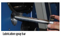
 7. Calculate lubrication requirements
Gears and bearings should be jet lubricated. All bearings and gears should employ interchangeable lubrication orifices that allow for easy replacement and flow adjustment without dismantling the gearbox.
Calculations are performed to ensure that lubrication applied to bearings meets or exceeds the manufacturers’ jet lube velocity parameters for proper lubrication penetration. Bearing losses due to heat are calculated and become factors in the overall lube system design for flow and cooling. Gear lube jet sizes are calculated to guarantee that all gear teeth receive adequate lube flow down to the roots of the teeth and that proper flow is maintained for heat removal.
All of the above calculations are then combined to size the central lubrication system flow, pressure, and cooling requirements.
8. Establish assembly procedures
Gearbox design must be practical as well as robust. Proper design will not only allow for ease of assembly, but must also provide for easy disassembly in cases of failure requiring component replacement. Access panels for visual inspection and maintenance can minimize disassembly during service.
9. Calculate efficiency
Gearbox efficiency will determine power losses, which when converted to heat, must be removed by the lube system’s cooling heat exchangers. Efficiency calculations will also ensure that input motors will provide sufficient power to overcome losses and result in correct gearbox output power.
10. Design instrumentation and routing locations
Gearboxes must be fully instrumented so that bearing and gear health is constantly monitored. This provides a troubleshooting tool as well as an early warning system of a potential problem.
All bearing arrangements must have thermocouples that report bearing operating temperatures to a master control and monitoring system. Any deviation from the acceptable temperature range must initiate an alarm and potential machine shutdown. Trend data should be recorded and the long-range performance of each bearing studied.
Input and output shaft, and fixed and floating bearing assemblies must be outfitted with accelerometers to measure shaft vibrations. Locating the accelerometers along the line of action between gears best measures maximum values. Accelerometer signals are also transmitted to the master control system where excessive values create alarms and shut down machine operation. Trend data is maintained for vibration information.
11. Complete assembly inspection documents
Complete inspection reports for every gearbox must be prepared in advance of assembly. These reports contain specific information and specifications about each bearing, shaft, and gear. Information such as shaft end play, gear backlash, bearing pre-load, and spacer data is recorded and compared to accepted values.
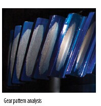
Assembler confirmation is required for various completeness and inspection tests. A smoke generator is used to confirm lubrication flow through piping and orifices and to detect leaks, and the results are recorded. A section of the inspection report is used to record gear contact patterns and still another section records bearing temperatures and accelerometer readings in the unloaded state as well as at 25%, 50%, 75%, and under full load.
These reports chronicle a baseline performance, ensure that gearboxes were assembled correctly and completely, and provide reference data for troubleshooting after machines are put into daily use.
12. Perform final acceptance testing
Before any machine can be shipped to a customer, an acceptance testing plan is established and the complete parameters of this plan must be met. Usually, machine performance criteria determine the elements of the acceptance plan.
It is important that the gearbox performance does not have any negative influence on the overall machine performance. This is ensured by carefully following the gearbox design steps above.
Learn more about the CSIA
RedViking is a member of the Control System Integrators Association (CSIA), which helps industries to have access to low-risk, safe, and successful applications of automation technology. CSIA helps its members improve their business skills, provides a forum to share industry expertise, and promotes best practices for business management.
Founded in 1994, CSIA is a not-for-profit, global trade association with more than 400 member firms in 27 countries.
www.controlsys.org
7. Calculate lubrication requirements
Gears and bearings should be jet lubricated. All bearings and gears should employ interchangeable lubrication orifices that allow for easy replacement and flow adjustment without dismantling the gearbox.
Calculations are performed to ensure that lubrication applied to bearings meets or exceeds the manufacturers’ jet lube velocity parameters for proper lubrication penetration. Bearing losses due to heat are calculated and become factors in the overall lube system design for flow and cooling. Gear lube jet sizes are calculated to guarantee that all gear teeth receive adequate lube flow down to the roots of the teeth and that proper flow is maintained for heat removal.
All of the above calculations are then combined to size the central lubrication system flow, pressure, and cooling requirements.
8. Establish assembly procedures
Gearbox design must be practical as well as robust. Proper design will not only allow for ease of assembly, but must also provide for easy disassembly in cases of failure requiring component replacement. Access panels for visual inspection and maintenance can minimize disassembly during service.
9. Calculate efficiency
Gearbox efficiency will determine power losses, which when converted to heat, must be removed by the lube system’s cooling heat exchangers. Efficiency calculations will also ensure that input motors will provide sufficient power to overcome losses and result in correct gearbox output power.
10. Design instrumentation and routing locations
Gearboxes must be fully instrumented so that bearing and gear health is constantly monitored. This provides a troubleshooting tool as well as an early warning system of a potential problem.
All bearing arrangements must have thermocouples that report bearing operating temperatures to a master control and monitoring system. Any deviation from the acceptable temperature range must initiate an alarm and potential machine shutdown. Trend data should be recorded and the long-range performance of each bearing studied.
Input and output shaft, and fixed and floating bearing assemblies must be outfitted with accelerometers to measure shaft vibrations. Locating the accelerometers along the line of action between gears best measures maximum values. Accelerometer signals are also transmitted to the master control system where excessive values create alarms and shut down machine operation. Trend data is maintained for vibration information.
11. Complete assembly inspection documents
Complete inspection reports for every gearbox must be prepared in advance of assembly. These reports contain specific information and specifications about each bearing, shaft, and gear. Information such as shaft end play, gear backlash, bearing pre-load, and spacer data is recorded and compared to accepted values.
Assembler confirmation is required for various completeness and inspection tests. A smoke generator is used to confirm lubrication flow through piping and orifices and to detect leaks, and the results are recorded. A section of the inspection report is used to record gear contact patterns and still another section records bearing temperatures and accelerometer readings in the unloaded state as well as at 25%, 50%, 75%, and under full load.
These reports chronicle a baseline performance, ensure that gearboxes were assembled correctly and completely, and provide reference data for troubleshooting after machines are put into daily use.
12. Perform final acceptance testing
Before any machine can be shipped to a customer, an acceptance testing plan is established and the complete parameters of this plan must be met. Usually, machine performance criteria determine the elements of the acceptance plan.
It is important that the gearbox performance does not have any negative influence on the overall machine performance. This is ensured by carefully following the gearbox design steps above.
Learn more about the CSIA
RedViking is a member of the Control System Integrators Association (CSIA), which helps industries to have access to low-risk, safe, and successful applications of automation technology. CSIA helps its members improve their business skills, provides a forum to share industry expertise, and promotes best practices for business management.
Founded in 1994, CSIA is a not-for-profit, global trade association with more than 400 member firms in 27 countries.
www.controlsys.org
1.The news above mentioned with detailed source are from internet.We are trying our best to assure they are accurate ,timely and safe so as to let bearing users and sellers read more related info.However, it doesn't mean we agree with any point of view referred in above contents and we are not responsible for the authenticity. If you want to publish the news,please note the source and you will be legally responsible for the news published.
2.All news edited and translated by us are specially noted the source"CBCC".
3.For investors,please be cautious for all news.We don't bear any damage brought by late and inaccurate news.
4.If the news we published involves copyright of yours,just let us know.


BRIEF INTRODUCTION
Cnbearing is the No.1 bearing inquiry system and information service in China, dedicated to helping all bearing users and sellers throughout the world.
Cnbearing is supported by China National Bearing Industry Association, whose operation online is charged by China Bearing Unisun Tech. Co., Ltd.
China Bearing Unisun Tech. Co., Ltd owns all the rights. Since 2000, over 3,000 companies have been registered and enjoyed the company' s complete skillful service, which ranking many aspects in bearing industry at home and abroad with the most authority practical devices in China.